Hacking A Remote Control Power Outlet
Messing around with 240V wiring isn't something I've ever been particularly eager to do, but I wanted a way to programmatically toggle one or more devices running on mains power.
If you've seen my 2015 Christmas Light post, you may have noticed that I have a bunch of traditional Christmas lights that aren't programmed in any way. I want to keep these for this year's display, but I have plans to make a display that synchronises to music. I want to turn the regular lights off when this display is active to maximise the impact.
Options...
There are a few ways to achieve this.
PowerSwitch Tail
PowerSwitch Tail is a range of kits that can be put together with two ends of a mains cable of your choosing. The kit has (low voltage) inputs that can be accessed by a microcontroller to effectively turn the power on and off.
The problem is, these kits are reasonably pricey and would presumably have to be ordered in from overseas. Also, there's still a degree of danger in wiring these things up.
Relay
The cheaper option would be to simply chop a mains cable in half and stick an appropriately rated relay in there. This is even more dangerous, and I prefer my house when it's not on fire.
Remote Control Switches
At the FinoComp office, we've just ordered in some components to create a neat continuous integration light based on a pedestrian crossing light. We're using two Z-Wave Switch Plugin units and a RaZberry daughterboard to control them.
This is probably the most reliable and safe method to achieve what I want, but at $65 a pop for the switches and $95 for the RaZberry, it's much more costly than what I want.
What, Then?
There's one final option. Take a cheap, remote control power outlet and hack it to support input from a microcontroller. As you may have guessed, this is the approach I ended up taking.
I bought an Arlec Remote Control Power Outlet from Bunnings for $13. The reason I chose this unit (apart from being cheap), is that it has separate "On" and "Off" buttons, which I assumed meant separate signals for turning the outlet on and off. This is very important, because the communication is typically unidirectional in these things.
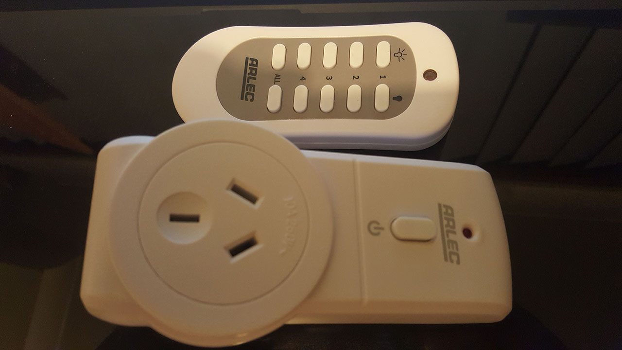
If the same signal is sent to toggle power and there's no way to know the state of the outlet, the state of the outlet may quickly become out of sync with what my software expects. Having separate signals means I can send the same signal a bunch of times to increase the likelihood of it being received.
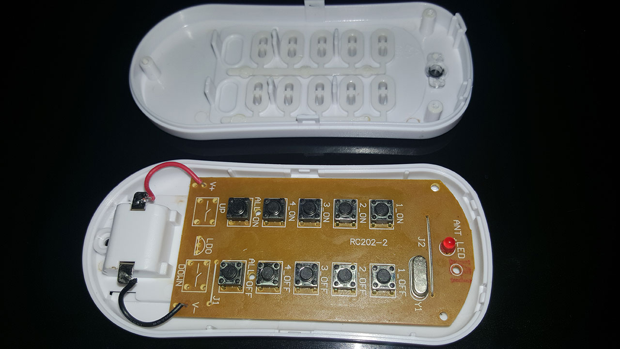
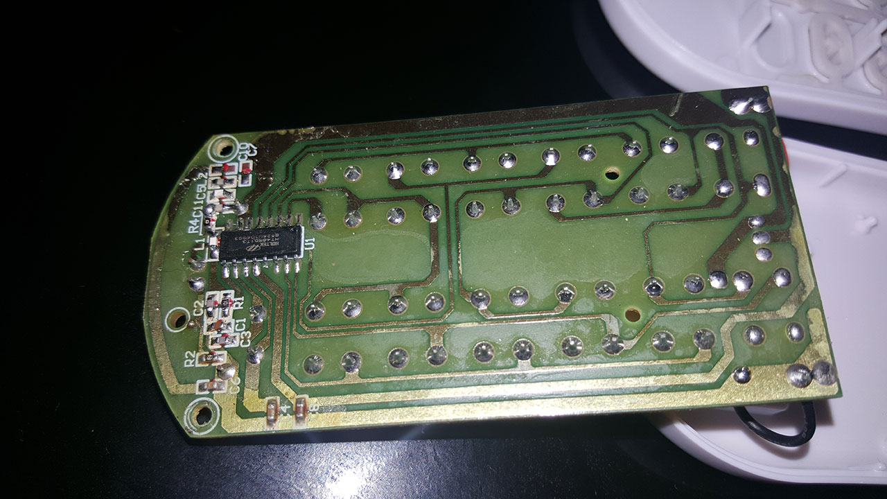
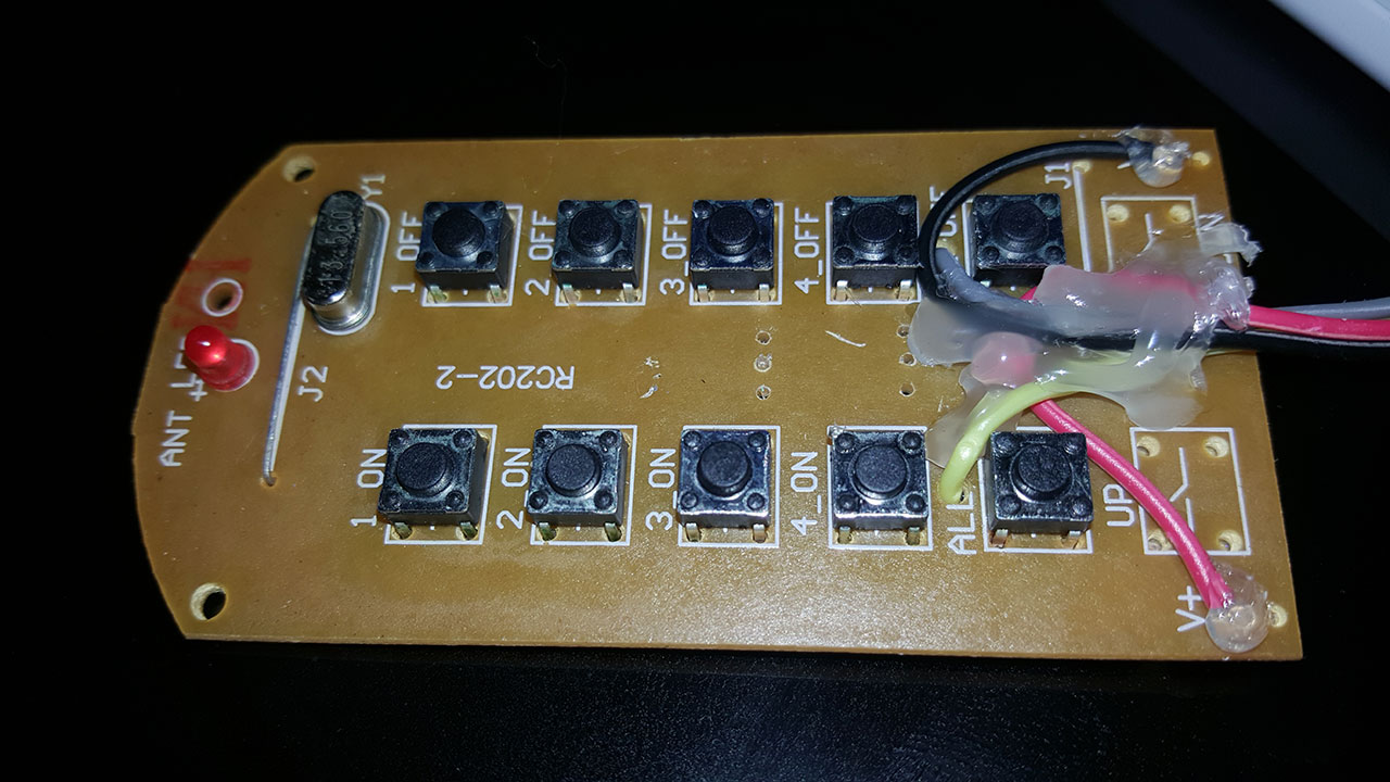
I cracked open the controller to see what I was dealing with. The quality of the circuit board isn't stellar, but it's good enough for my purposes. The circuit itself isn't too complex. Basically a bunch of buttons attached to a Holtek HT48R01T3 MCU, which contains an RF transmitter.
Now, there are various blog posts around the place that detail ways to capture IR signals, send them through a PC microphone jack and analyse their waveforms in order to reproduce the signals.
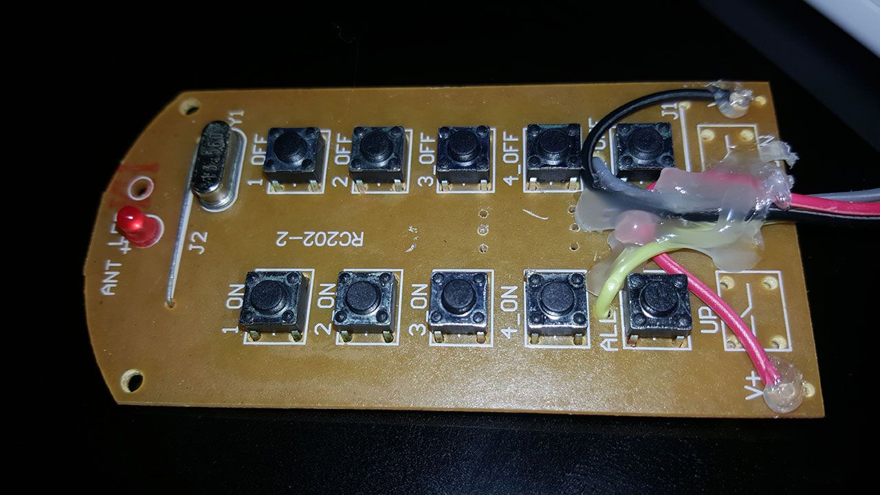
Thing is, I'm too lazy to do all that if it can be avoided. I decided to simply rewire the "All On" and "All Off" buttons to allow me to control them from an Arduino Due.
Rewiring The Controller
I ended up adding four wires in total. Two of these wires were simply to allow the remote to be powered by my Arduino Due instead of using batteries. The remote ran from two 1.5V LR44 batteries in series. The Arduino Due works with 3.3V, which is close enough for me. Of course, I measured the current draw through the remote before trying this. It was only 8mA, which is a small enough amount to run through the Arduino without blowing it up.
The other two wires were added to the positive side of the "All On" and "All Off" buttons, respectively. I worked out which side of the buttons were the positive side using the DC voltage mode on my multimeter.
These pins are connected to the Arduino, and are kept high. When one of the pins is brought low, the button is effectively circumvented, completing the circuit and allowing the signal to be sent. The nice thing about my approach is that the buttons can still be used, even when the controller is connected to the Arduino.
I finished the job by applying hot glue to prevent the wires from moving about and breaking. It's ugly, but I don't need it to be pretty for what I'm doing.
The Code
I've only written a basic test program to ensure the controller can turn the outlet on and off. Here it is for completeness:
#define ON_PIN 22
#define OFF_PIN 23
#define TIME_BETWEEN_POWER_TOGGLE_MS 5000
#define MESSAGE_DURATION_MS 500

void setup() {
    pinMode(ON_PIN, OUTPUT);
    digitalWrite(ON_PIN, HIGH);

    pinMode(OFF_PIN, OUTPUT);
    digitalWrite(OFF_PIN, HIGH);
}

void loop() {
  turnOn();
  delay(TIME_BETWEEN_POWER_TOGGLE_MS);
  turnOff();
  delay(TIME_BETWEEN_POWER_TOGGLE_MS);
}

void turnOn() {
    sendMessage(ON_PIN);
}

void turnOff() {
    sendMessage(OFF_PIN);
}

void sendMessage(int pin) {
  digitalWrite(pin, LOW);
  delay(MESSAGE_DURATION_MS);
  digitalWrite(pin, HIGH);
}
The Finished Product
Here's a video of the controller in action.